
Choosing Capscrew Counterbores for international projects requires more than matching a catalog photograph. The right component must fit the screw head, material thickness, machining method, and assembly environment. A counterbore that looks correct may leave a cap screw exposed by two millimeters. That small error can interfere with a cover, seal, or moving assembly. Global buyers also face different thread systems, drawing standards, surface finishes, and supplier naming conventions. Clear specifications matter.
This guide explains how to compare Capscrew Counterbores with practical purchasing criteria. It considers diameter, depth, tolerance, pilot size, material grade, coating, and tool compatibility. For example, a stainless steel counterbore used near moisture may need different protection than a hardened tool steel version used in a production jig. Experienced buyers should request dimensional drawings, inspection records, sample parts, and material certificates. Supplier feedback is useful, but it should not replace independent verification. Small details matter.
No selection method is perfect. Real assemblies sometimes reveal clearance problems that drawings overlook. A trial installation can expose burrs, poor seating, or difficult tool access before full production begins. Buyers should document these findings and revise their specifications when necessary. Reliable sourcing depends on repeatable measurements, transparent communication, and realistic quality expectations. The goal is not simply to find the lowest price. It is to secure a counterbore that performs consistently across suppliers, locations, and production cycles.
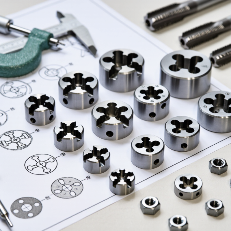
How to Choose Capscrew Counterbores for Global Buyers?
Capscrew counterbores create a recessed seat for socket head screws. They protect the screw head and leave a smooth surface for moving parts. ISO 4762 defines common socket head cap screw dimensions, but the counterbore still needs separate verification. For example, an M6 screw commonly uses a head diameter near 10 mm. A practical counterbore may need extra clearance for installation tools. Material also matters. Aluminum needs controlled depth and edge distance, while hardened steel tolerates higher contact pressure.
Global applications often combine different drawing standards, suppliers, and machining capabilities. The 2024 Global Industrial Fasteners Market report places the sector above USD 90 billion in 2023 and forecasts continued growth through 2030. That scale increases the need for consistent hole specifications. Buyers should state screw standard, nominal diameter, counterbore diameter, depth, tolerance, and surface finish. Do not rely on “standard counterbore” alone. Fit is not universal. ASTM F835 covers certain alloy-steel socket screws, but its requirements do not replace a complete machining drawing. A perfect selection on paper can still fail during assembly.
Tips: Measure twice. Use a depth gauge and a sample screw before approving production. Check tool access, burr formation, and minimum wall thickness. Keep dimensions in millimetres, even when suppliers use imperial tools. Ask for inspection records based on the drawing, not verbal confirmation. Regional catalogs can differ slightly, so compare the actual screw head dimensions first. The overlooked detail is often the counterbore shoulder.
Choosing capscrew counterbores starts with the screw head, not the cutting tool. Socket head cap screws usually need a cylindrical recess with a flat shoulder. A spotface may work when only a small seating area is required. A stepped counterbore suits concealed fasteners and deeper head clearance. Confirm the pilot diameter, recess diameter, and cutting depth from the screw drawing.
Size selection must account for tolerances, coatings, and installation tools. Metric and inch dimensions should never be mixed casually. A recess that is only slightly undersized can trap the screw head. Excessive clearance can weaken a thin plate. Measure the actual screw batch when possible. It is a small step.
Material choice depends on both the workpiece and production volume. High-speed steel can suit occasional work in aluminum or mild steel. Carbide offers better wear resistance for hardened steel, stainless steel, or repeated machining. A suitable coating may reduce friction, but it cannot correct poor speeds or feed settings. Use rigid holders and coolant when heat becomes visible. That detail is often missed.
Global buyers should request a drawing showing dimensions, tolerance, pilot geometry, shank size, and inspection method. Specify whether the tool is intended for drilling, milling, or hand operation. Ask for material certificates and sample inspection records when consistency matters. I have seen purchasing decisions focus on price while ignoring recess depth control. That choice usually becomes expensive during assembly. Recheck the design.
Practical selection guide for socket head capscrews. Dimensions below are typical engineering starting values in millimetres; final dimensions should be checked against the selected screw standard, tolerance class, coating, washer arrangement, and installation tool.
| Counterbore Type | Common Application | Screw Size | Clearance Bore Ø mm |
Counterbore Ø mm |
Recommended Depth mm |
Suitable Workpiece Materials | Selection and Inspection Notes |
|---|---|---|---|---|---|---|---|
| Metric Socket Head Capscrew Counterbores — Typical Clearance Dimensions | |||||||
| Straight cylindrical counterbore | General machine assemblies where the capscrew head must sit below or flush with the surface. | M3 | 3.5 | 6.5 | 3.5 | Aluminium, steel, stainless steel, engineering plastics | Use a flat-bottomed counterbore. Increase depth only when surface protection or a cover requires additional head clearance. |
| Straight cylindrical counterbore | Compact equipment, instrument panels, and light-duty brackets. | M4 | 4.5 | 8.0 | 4.5 | Aluminium alloys, mild steel, glass-filled polymers | Allow extra radial clearance when screws are inserted before a mating part is aligned. |
| Straight cylindrical counterbore | Fixtures, guards, covers, and general-purpose machine frames. | M5 | 5.5 | 9.5 | 5.5 | Aluminium, carbon steel, stainless steel, acetal | Check that the remaining wall around the counterbore is strong enough for the applied clamp load. |
| Straight cylindrical counterbore | Structural joints, mounting plates, and medium-load assemblies. | M6 | 6.6 | 11.0 | 6.5 | Steel, aluminium, ductile iron, reinforced polymers | A common size for industrial equipment. Confirm head diameter and head height for the chosen capscrew specification. |
| Deep cylindrical counterbore | Heavy brackets, machine bases, and locations requiring a protected fastener head. | M8 | 9.0 | 15.0 | 8.5 | Steel, cast iron, aluminium with sufficient section thickness | Use only where the available material thickness can accommodate the counterbore without weakening the joint. |
| Deep cylindrical counterbore | High-load frames, tooling plates, and mechanically protected joints. | M10 | 11.0 | 18.0 | 10.5 | Steel, cast iron, high-strength aluminium sections | Inspect the counterbore bottom for tool marks, burrs, and adequate flat seating under the screw head. |
| Deep cylindrical counterbore | Large machine structures, lifting fixtures, and heavy mounting connections. | M12 | 13.5 | 21.0 | 13.0 | Steel, cast iron, thick aluminium sections | Consider a washer or hardened seating insert when the parent material has low surface hardness. |
| Inch Socket Head Capscrew Counterbores — Typical Clearance Dimensions | |||||||
| Straight cylindrical counterbore | Small assemblies, electronic equipment, and light-duty brackets. | 1/4 in | 0.281 in | 0.500 in | 0.280 in | Aluminium, steel, plastics | Use a standard clearance hole unless positional accuracy or sliding assembly requires a larger hole. |
| Straight cylindrical counterbore | General machinery, fixtures, guards, and mounting plates. | 5/16 in | 0.344 in | 0.625 in | 0.340 in | Steel, aluminium, cast iron, reinforced plastics | Confirm whether the fastener uses a standard or reduced-head configuration before fixing the counterbore diameter. |
| Straight cylindrical counterbore | Medium-load structural connections and machine bases. | 3/8 in | 0.406 in | 0.688 in | 0.400 in | Steel, stainless steel, aluminium alloys | Provide sufficient edge distance to prevent breakout around the counterbore opening. |
| Deep cylindrical counterbore | Heavy brackets, tooling, industrial frames, and protected fastener installations. | 1/2 in | 0.531 in | 0.875 in | 0.520 in | Steel, cast iron, thick aluminium sections | Check section thickness, screw head height, coating buildup, and access for the hex key or driver. |
| Material, Finish, and Manufacturing Requirements | |||||||
| Hardened tool steel counterbore cutter | High-volume production in steel or cast iron components. | Metric or inch | According to cutter guide | Matched to cutter pilot | Set by screw head height | Carbon steel, alloy steel, cast iron | Resists wear and maintains diameter. Use suitable cutting fluid and remove burrs after machining. |
| Carbide or carbide-tipped tool | Abrasive alloys, hardened materials, composites, or long production runs. | Metric or inch | According to cutter guide | Matched to cutter pilot | Set by design requirement | Hardened steel, glass-filled polymers, abrasive composites | Provides improved wear resistance but requires rigid setup, correct feed rate, and protection against chipping. |
| Replaceable-pilot counterbore | Global production with multiple screw sizes or frequent tool changes. | M3–M12 and equivalent inch sizes | Interchangeable pilot | Interchangeable cutter | Adjustable or programmed | Most machinable metals and plastics | Useful for maintaining concentricity. Verify pilot fit, runout, and replacement-part compatibility. |
| Spotface-style shallow counterbore | Creating a flat bearing surface for a capscrew head on a rough, curved, or cast surface. | Selected screw size | Standard clearance | Slightly larger than head diameter | Minimum depth needed for a flat seat | Castings, forgings, rough-machined steel, aluminium | Do not use a shallow spotface when the design requires complete head concealment or cover clearance. |
| Blind counterbore | Sealed housings, thin-wall parts, and applications where the opposite surface must remain intact. | Selected screw size | Standard clearance | Based on head diameter | Head height plus installation clearance | Aluminium, steel, plastics, composite panels | Control depth carefully to avoid breakthrough. Specify a bottom radius or relief if the cutter geometry requires it. |
| Buyer Verification Checklist for International Sourcing | |||||||
| Dimensional standard | Confirm the capscrew standard and nominal size. | Metric or inch | Do not combine a metric screw with an inch counterbore specification without checking actual head diameter, head height, and clearance requirements. | ||||
| Fastener head clearance | Measure or obtain the maximum screw head dimensions. | Radial clearance: typically 0.25–0.75 mm for general assembly | Use a larger allowance for painted, plated, coated, or manually aligned assemblies. | ||||
| Edge distance | Protect the material around the opening. | Prefer at least one counterbore radius from the nearest free edge | Reduce the counterbore diameter or redesign the joint if the remaining wall is too thin for the applied load. | ||||
| Surface and burr control | Ensure full, stable seating of the capscrew head. | Flat bottom, clean shoulder, controlled chamfer | Remove burrs without creating a chamfer large enough to reduce the effective bearing area. | ||||
| Material compatibility | Match tool, workpiece, and corrosion requirements. | Steel, carbide, or coated tooling as appropriate | For stainless steel or aluminium, use suitable cutting conditions and consider galvanic corrosion when selecting the fastener and workpiece materials. | ||||
How to Choose Capscrew Counterbores for Global Buyers?
Matching Counterbores with International Capscrew Standards
Global sourcing makes counterbore selection less simple than reading a screw diameter. ISO 4762 and DIN 912 define metric hexagon socket head capscrews. ASME B18.3 covers common inch-based designs. Their head diameters and heights are not interchangeable. For example, an M8 ISO 4762 screw has a nominal 13 mm head diameter and 8 mm head height. A 1/4-inch ASME capscrew uses inch dimensions. Converting units alone can create a poor fit.
Use the applicable standard’s maximum head dimensions, not only nominal values. Add controlled radial clearance for plating, paint, burrs, and tool wear. Counterbore depth should exceed the measured head height slightly, while preserving enough material beneath the recess. ISO 273 clearance-hole tables can guide the through-hole, but they do not replace the capscrew standard. A 2024 global fastener market report projects continued cross-border demand, while UN Comtrade data shows extensive international hardware movement. Specification discipline matters.
In production inspections, actual batches often differ slightly. That detail is easy to ignore. I would verify ten samples before releasing a drawing. Measure head diameter, head height, and coating thickness. Then record the selected standard beside the counterbore callout. A universal counterbore rule sounds efficient, but it is not fully reliable. Metric and inch parts may appear close, yet assembly forces can expose the mistake. Include the standard, size, tolerance, depth, and finish condition. That information helps overseas machinists reproduce the intended fit.
Matching counterbores with international socket head capscrew standards
The chart compares socket head diameter values from ISO 4762 metric capscrews and ASME B18.3 inch capscrews with a practical starting-point counterbore diameter. The counterbore recommendation is calculated as the standard head diameter plus approximately 0.5 mm clearance; final sizing should also consider coating thickness, burrs, installation access, and the selected tool.
When selecting capscrew counterbores, tool quality starts with geometry, runout, and edge consistency. A cutting edge that looks sharp may still produce a rough seat. ISO 286-1 tolerance grades help buyers specify dimensional limits, but they do not guarantee stable performance during heat buildup. Check the pilot diameter, cutting diameter, concentricity, and surface finish separately.
Tolerance is only useful when linked to the fastener and assembly load. For general steel work, many buyers target counterbore diameter control within 0.02–0.05 mm, depending on design requirements. That range is not universal.
A 2022 CIRP Journal review reported that coated carbide tools can improve wear resistance by roughly 20–50% in controlled machining tests. Coatings still depend on speed, feed, coolant, and substrate. A perfect coating cannot rescue poor geometry.
Service life also reflects material availability and maintenance planning. The USGS Mineral Commodity Summaries 2024 reported approximately 81,000 metric tons of global tungsten mine production in 2023. This reinforces the value of choosing carbide carefully rather than replacing tools casually.
Inspect the first and fiftieth holes. Compare burrs, diameter drift, and edge chipping. I would not trust a claimed tool life without a defined workpiece, machine, and cutting schedule. Real factories are less tidy. Recheck the numbers.
For global buyers, a capscrew counterbore supplier should provide more than a dimensional drawing. Request material certificates, hardness results, coating details, and inspection records for every production batch. ISO 9001 certification can support process control, but it does not replace product-specific evidence. Check cavity diameter, depth tolerance, surface finish, and tool life against your actual fastener design. A supplier’s sample should be tested with the intended capscrew, not an easier substitute.
Compliance documents must match the destination market and shipment contents. Ask for a certificate of conformity, traceability records, restricted-substance declarations, and the correct customs classification. The World Bank’s 2023 Logistics Performance Index shows that customs efficiency, tracking, and delivery reliability strongly influence international logistics performance. Missing paperwork can therefore create more risk than a small price difference. It happens.
Shipping terms need equal attention. Compare air freight, ocean freight, and consolidated cargo using total landed cost, not only the supplier’s unit price. UNCTAD’s Review of Maritime Transport reports that ships carry over 80% of global merchandise trade by volume, yet port congestion and schedule changes remain practical concerns. For urgent tooling, air freight may protect production continuity. For repeat orders, sea freight may reduce cost, but packaging must prevent corrosion, edge damage, and mixed-lot confusion. Confirm carton dimensions, pallet limits, insurance responsibility, and tracking milestones before payment. A written delivery plan is useful, though it can still fail during peak seasons. Recheck it.
It creates a cylindrical recess for a socket head screw. The screw head sits below the surface. This protects the head and leaves room for moving parts.
Start with the actual screw head dimensions, not the cutting tool. Check the recess diameter, pilot diameter, depth, and shoulder. For an M6 screw, the head may measure near 10 millimetres. Allow extra tool clearance.
No. Fit is not universal. Screw batches, coatings, and regional drawings may differ slightly. Measure a sample screw before production approval. Small differences can cause assembly problems.
Use a cylindrical recess with a flat shoulder for most socket head screws. A spotface suits shallow seating needs. A stepped counterbore provides deeper head clearance. Confirm the screw drawing first.
Check minimum wall thickness and edge distance before machining. Excessive clearance can weaken thin plates. Aluminum needs controlled depth and careful shoulder placement. Hardened steel can tolerate higher contact pressure.
High-speed steel can suit occasional work in aluminum or mild steel. Carbide generally lasts longer in hardened or stainless steel. A coating may reduce friction, but it cannot fix poor cutting settings. Heat is a warning.
Request a complete drawing with dimensions, tolerances, shank size, pilot geometry, and inspection methods. Ask for material certificates and sample inspection records. Verbal confirmation is not enough. Recheck the critical shoulder.
Use a depth gauge and the intended screw. Check diameter, depth, burrs, tool access, and surface finish. Inspect several pieces from each batch. A perfect drawing can still fail during assembly.
Confirm conformity documents, traceability records, restricted-substance declarations, and customs details. Compare air, sea, and consolidated freight using total landed cost. Protect cutting edges from impact and moisture. Delivery plans can still slip.
The counterbore shoulder is often overlooked. A poor shoulder can leave the screw uneven or unstable. I would measure it twice. That small check may prevent an expensive rework.
Choosing the right Capscrew Counterbores is essential for global buyers who need clean recesses, accurate fastener seating, and consistent assembly performance. Start by understanding the application, including the material being machined, required hole depth, access conditions, and expected production volume. Compare counterbore types, dimensions, pilot configurations, and construction materials to ensure compatibility with the workpiece and intended capscrew. It is also important to match the tool’s geometry and size range with internationally recognized capscrew standards, while allowing for regional measurement preferences and engineering requirements.
Before purchasing, evaluate manufacturing quality, dimensional tolerance, cutting performance, surface coatings, and expected service life. Reliable suppliers should provide clear technical specifications, inspection information, material details, and appropriate compliance documents. Buyers should also review customization capabilities, packaging protection, lead times, communication support, and shipping options. A careful comparison of technical fit, documentation, total cost, and after-sales service can help global customers select counterbores that deliver dependable results across different equipment, markets, and production environments.